Functional Specification
The PDU is a dual channel, redundant, EASA CS-LURS Compliant aircraft electrical system in a single box.
It embeds Primary and Secondary Power distribution system, plus battery charging and 14V DC/DC converter functionality.
It just requires few connections to power sources and loads to be ready. It is split in two main parts: the Primary Side and the Backup Side, which are mechanically and electrically segregated, in order to maximize reliability trough redundancy. The Primary Side is able to manage over 2.000 Watt of electrical power, while the Backup Side manages 1.500 Watts. Primary plus Backup side allows connection to 48 loads.
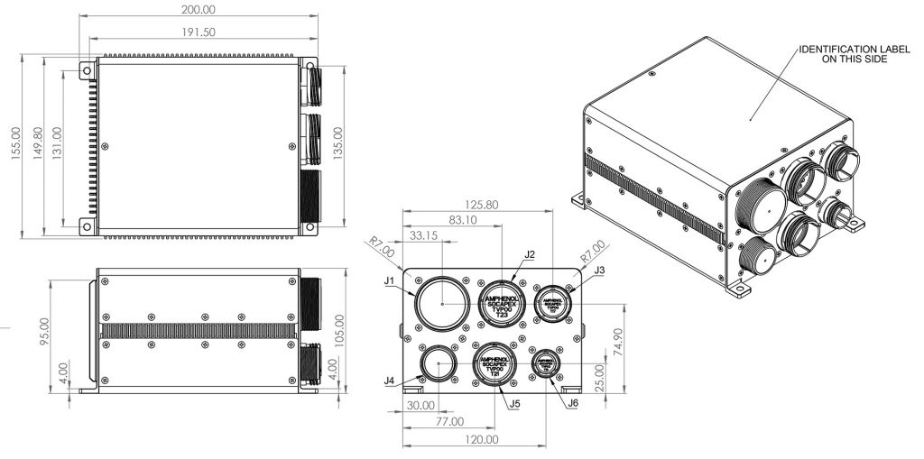
All power and signal interfaces are routed through MIL 38999 Aerospace standard connectors, in order to grant wide compatibility and ease of installation.
Primary Side:
On the Primary side, three 28V, 70A+ power inputs are available, typically: Starter/Generator, External Receptacle and Aircraft Battery. All input sources are protected against overvoltage and reverse polarity, while voltages and currents can be digitally monitored. Source selection among the three inputs is controlled via validity windows and pre-programmed priority.
Primary Side has 30 e-CB power outputs. e-CB uses a Brancaro Industries proprietary technology to implement a smart Solid-state circuit breaker with embedded switch function. Each e-CB rating can be set according to customer specification, available e-CB ratings are: 1A, 2.5A, 7.5A, 10A and 15A.
Primary Side signal section is supervised and controlled by a microprocessor-based Logic board, which is also equipped with:
- 12 Open/GND Input Discretes
- 2 28V/Open Input Discretes
- 6 Open/GND Output Discretes (2 of them PWM-enabled)
- 2 28V/Open Output Discretes
- 2 +/- 10V Differential Analog Input
- 2 PT1000 Temperature Input
- 1 CAN-BUS
- 1 RS-422/485 Full duplex Bus
- 1 Maintenance Port (used with Windows Maintenance App and SW Updates)
Backup Side:
The Backup Side is designed to operate in a stand-alone mode or to support the aircraft safety features when the Primary Side fails or behaves unexpectedly. If this feature is enabled, the Backup Side power outputs shall be connected to critical loads, via diodes.
On the Backup side, two 28V, 35A+ power inputs are available, typically: Starter/Generator and Aircraft Battery. All input sources are protected against overvoltage and reverse polarity. Source selection among the three inputs is controlled via validity windows and pre-programmed priority.
Backup Side has 18 e-CB power outputs. e-CB uses a Brancaro Industries proprietary technology to implement a smart Solid-state circuit breaker with embedded switch function. Each e-CB rating can be set according to customer specification, available e-CB ratings are: 1A, 2.5A, 7.5A, 10A and 15A.
Backup Side signal section is supervised and controlled by a hard-wired, simple logic board, which is also equipped with:
- 6 Open/GND Input Discretes
- 2 28V/Open Input Discretes
- 4 Open/GND Output Discretes
- 1 28V/Open Output Discretes